Tabela de conteúdos
Introdução
Esse tutorial tem como propósito ser uma primeira introdução à modelagem 3D usando a Bancada Part  Switch_PartWorkbench.JPG do FreeCAD. Ao finalizá-lo você deve estar apto a produzir modelos 3D simples usando primitivas, como cubos, cilindros, etc, com a técnica de modelagem chamada Geometria Sólida Construtiva (ou Constructive Solid Geometry, CSG, em inglês). Uma outra maneira de criar modelos 3D é usando uma forma 2D, por exemplo, fazendo a extrusão dela ou revolução da forma 2D no espaço 3D. Para uma introdução nessa técnica, por favor acesse o tutorial irmão
 Creating a simple part with PartDesign. Esses dois tutoriais tem, intencionalmente, o mesmo modelo gerado, para apresentar ao iniciante uma experiência com a mão na massa nas duas diferentes técnicas e como são implementadas no FreeCAD.
A definição das duas técnicas pode ser vista como estritamente dividida do ponto de vista semântico, no entanto, não há nada impedindo diretamente uma mistura delas ao criar modelos. Há algumas ressalvas a serem observadas ao misturar técnicas de modelagem, principalmente relacionadas a aspectos de como o FreeCAD é programado. Há um terceiro tutorial, feito como uma primeira introdução a um exemplo de modelagem mista. Esse tutorial utiliza a 'Bancada Draft' para criar um perfil 2D utilizado para extrudar um sólido na 'Bancada Part' para fazer o mesmo modelo deste tutorial.
Antes de começar, dê uma olhada em como 'navegar' no espaço 3D. Ao passar o mouse sobre o seletor de modo do mouse no canto inferior direito da janela do FreeCAD, dicas do modo atual de operação do mouse aparecem como na imagem abaixo.

Muitos novatos em programas CAD travam ao aprender o software. Se isso acontecer com você, por favor, procure mais informações na wiki ou no fórum - é provável que outras pessoas também tenham travado no mesmo ponto, então já pode existir uma resposta para a sua pergunta. Ou faça um post no fórum com suas perguntas ou descobertas. O fórum possui vários tópicos onde os usuários obtém ajuda para concluir todo tipo de tarefa, esses tópicos muitas vezes são semelhantes a tutoriais e frequentemente incluem ilustrações.
O que esse tutorial cobre
- O modelo a ser criado
- Usando da Bancada Part para criar e manipular os modelos primitivos
- Alterando cor e transparência
- Um modo diferente de posicionar o buraco
- Tornando o furo um furo escareado (ou rebaixado)
- Fazendo uma peça oca
- Uma maneira diferente de posicionar o chanfro
- Editando dimensões
- Organizando a árvore ligeiramente diferente
- Finalizando
O modelo a ser criado

Usando da Bancada Part para criar e manipular os modelos primitivos
Crie um novo documento e salve-o lodo com um novo nome. É uma boa prática garantir que você salve o documento em intervalos regulares ou antes de operações maiores. Em seguida, mude para a 'Bancada Part' usando o seletor de bancadas (rotulado como 10 na imagem vinculada) ou indo para o menu Vista → Bancada. O FreeCAD iniciará com as barras de ferramentas na parte superior, a 'Tela combinada' à esquerda e a vista 3D à direita.
Create the main solid block
Press 24px|link=Part_Box Box to make a default solid cube. The cube appears in the 3D view and also as a new object in the Tree view in the sidebar.
Press 24px|link=Std_ViewIsometric Isometric to see the cube in 3D.
</translate> center <translate>
Select the cube in the Tree view, it becomes green in the 3D view. Below the tree view you will now see that the cube by default is created with the dimensions 'Length x Width x Height' as 10 x 10 x 10 mm. Change those dimensions to '100 x 30 x 50' as per the initial drawing of the model.
</translate> center <translate>
When changing a property, like Length through the spinbox, one can either enter the values, or use the scroll-wheel to tick values up or down. The arrows for ticking values up or down can of course also be used. In the right most picture above, the Height property is in edit mode, rolling the scroll wheel when the mouse is over that cell will change the value by one up or down.
<!–T:16–>
Click 24px|link=Std_ViewFitAll 'Fit all' to see the whole cube.
</translate> center <translate>
Crie o arredondamento
Para criar o canto arredondado, na barra de ferramentas, clique em 'Filete' (ou 'Fillet'), o que abre o painel de tarefas para arredondamentos na 'Tela combinada' na lateral. Mude a caixa de seleção do raio para 20 mm e, em seguida, na vista 3D, selecione a borda na lateral superior à direita e clique em OK.
To make the filleted corner, in the toolbar press 24px|link=Part_Fillet 'Fillet' which opens the task panel for fillets in the combo view to the side. Change the radius spinbox to 20 mm, then in the 3D view, select the width edge to the upper right and click OK.
</translate> center <translate>
<!–T:19–>
The task panel closes and you are back to the Tree view which now has a fillet object instead of the earlier cube.
Visibility of children
<!–T:21–>
Click the plus sign/caret to expand the children of the fillet, which in this case is the cube we created earlier, but it is grayed out. Select the cube and press the space bar – this toggles visibility so the cube is now visible again and the icon is no longer grayed out. To deselect the cube click in a blank area in the Tree view or the 3D view.
</translate> center <translate>
Create the chamfer
<!–T:23–>
Next is to create the 30 degree chamfer, start by toggling the visibility of the child cube of the fillet. There is a chamfer tool in Part Workbench, but instead of using it we will make the chamfer with another block and a boolean cut.
<!–T:24–>
Create a new 24px|link=Part_Box 'Box' with dimensions 60 x 30 x 30. Change the 'placement angle' to -30 degrees.
</translate> center <translate>
<!–T:25–>
The placement angle is using the 'placement vector' (Axis) as axis of rotation. The default is the z-axis, which is not matching our target direction, changing the placement vector to the 'y-axis' produces the desired orientation of the cutting tool for the chamfer.
</translate> center <translate>
<!–T:26–> The same placement can be attained with other values as well, the simplest alternative example of a placement that is the same is an angle of +30 degrees and a y-axis of -1.
Python console
<!–T:28–>
Furthermore the position needs to be adjusted, looking at the drawing of the finished part, there is no direct dimension to use for the intended translation upwards. Since the upward dimension is the one needed, we have to calculate it. Let’s make use of the built in 'Python console' for those calculations, it is basic trigonometry. If the FreeCAD Python console is not visible for you, just right-click in an empty space in the toolbar area and check the Python console and it should appear in the workspace, when there you should as well add the 'report view' if not already visible. The report view most of the times provides useful information or even hints of what to do next for different commands.
</translate> center <translate>
<!–T:29–>
After importing the '[https://docs.python.org/3/library/math.html#module-math math]' module from the standard libraries in python we can use the formula (50 - math.tan(math.radians(30)) * 50) to find the distance in z-direction that the block should be moved. Copy the result of the formula from the Python console and paste it into the z position for 'Cube001'. The tool to use for the chamfer cut is now properly oriented and positioned.
</translate> center <translate>
====Expressions==== <!–T:30–>
<!–T:31–>
One does not have to use the Python console to do the calculation, In most cases when dealing with numeric parametric values, FreeCAD has a short-cut to a built-in calculator. It is called 'Expressions' in FreeCAD, you can enter the expression mode by first clicking in the spinbox for the z-position, a small blueish circular icon will appear at the right side.
</translate> center <translate>
<!–T:32–>
Clicking that icon opens new window Formula editor where formulas and expressions can be entered as shown below. Using expressions is a powerful tool, since one can access parameters from the model, effectively making all parameters in the model available as variables to be used when creating an expression. In short, in our formula, instead of entering the number 50 when in the formula editor, we could enter a named parameter holding the value 50 from the cube, with the benefit that if we change the cube height, the position of the chamfer will automatically follow. The value of 50 in the current model is referred to as Cube.Length, i.e. the Length property of the Cube feature. Further information on this can be found on the wiki.
</translate> center <translate>
<!–T:33–>
To make the cut, with the Ctrl key pressed down first select the 'Fillet' in the Tree view and then the latest created cube (named 'Cube001') and finally in the toolbar press the 24px|link=Part_Cut 'Cut' button. Your Tree view should now again be a single object in the root called 'Cut'.
</translate> center <translate>
====The toolbars==== <!–T:102–>
<!–T:103–> A sidenote on the toolbars, since they are the typical avenue to invoke commands. Although there is a basic setting for the layout of the toolbars, the actual layout on your computer could turn out to be less than ideal. In such cases it is easy to adjust. Consider the upper section of the below image. There are two rows of toolbars and only a limited number of the Part Workbench toolbar buttons are visible. The simplest way to see more toolbar buttons is to maximize the FreeCAD window, unless it already is maximized of course.
<!–T:104–> More common is to adjust the layout of the toolbars to suit your needs and your specific computer. The repositioning is done with the handle on the left of each toolbar. You can just click and drag the handle to a new location. In the lower section of the below image the toolbar positions have been adjusted, revealing their full content. Changes to toolbar positions are persistent through sessions.
</translate> center <translate>
====The measurement tool==== <!–T:34–>
<!–T:35–>
The 'measurement tool' in the 'Part Workbench' can be used to check that our calculation and placement of the chamfer is correct. Press the 24px|link=Part_Measure_Linear 'Measure Linear' button and a task panel opens up, then select the 2 endpoints of one side of the chamfer.
</translate> center <translate>
<!–T:36–> It checks out with an x dimension of 50 mm, clear the measurement and close the dialogue.
===Create the hole=== <!–T:37–>
<!–T:38–>
To make the hole, press the 24px|link=Part_Cylinder 'Cylinder' button, set the radius to 5 mm and height to 50 mm.
</translate> center <translate>
<!–T:39–>
Next we need to position the hole according to the dimensions in the drawing. Change the view to 24px|link=Std_ViewTop 'Top' view, then right-click the 'Cylinder' in the Tree view and select 'Transform' from the pop-up menu.
</translate> center <translate>
<!–T:40–>
Change the Translation increment to 5 and use the red and green arrow to position the cylinder in the right position, moving it 15 mm in y and 65 in x by dragging the arrow ends with the mouse. Click OK to close the Transform dialogue. To make the hole press the Ctrl key and select the 'Cut' and 'Cylinder' in the Tree view, then press the 24px|link=Part_Cut 'Cut' button in the toolbar. Your Tree view should once again have a single object in the root called 'Cut001'.
<!–T:41–> Congratulations, the model is now ready.
</translate> center <translate>
<!–T:42–> With the basic model ready, let us explore different ways to alter this model, some examples are related to the appearance, additional features, or simply a different way to do the same.
==Changing the color and transparency== <!–T:43–>
<!–T:44–>
There are several different ways one can change the appearance of objects, for this case, let's use the view tab in the property part of the combo view. First select the object in the Tree view and then edit any property like line color, shape color or transparency via the 'view tab' (found at the bottom of the combo view).
</translate> center <translate>
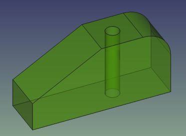
<!–T:45–> Unfortunately when the object is selected it is a bit hard to see how it will look when tuning the new appearance. To see the final result one has to deselect the object. Here is the new look of the model, where one now can see the through hole also in the iso-view. Another way to edit the appearance is via the View → [[Image:Std_SetAppearance.svg|24px|link=Std_SetAppearance]] Appearance... menu.
</translate> center <translate>
==A different way to locate the hole== <!–T:46–>
<!–T:47–>
Do a save-as under a new name. Then delete the cut that added the hole and move the cylinder back to zero position. Your model should look like the below picture, which is the starting point for using a different technique to locate the hole at the center of the upper face. Note that the color is back to the default gray, the change in appearance we did was on the cut object which now is deleted.
</translate> center <translate>
<!–T:48–>
This time the 24px|link=Draft_Workbench 'Draft Workbench' will be used to locate the hole. The hole is as before to be located at the center of the upper face, which is the same as the midpoint of the diagonal of the upper face.
<!–T:97–>
Start by switching the workbench to 'Draft', it might be that a grid appears in the 3D view, the grid visibility can be toggled with 24px|link=Draft_ToggleGrid Toggle Grid in the toolbar. When making use of the 'snap' functionality in the 'Draft Workbench' it helps to only have the snap types of interest enabled. This time it is sufficient to leave endpoint, midpoint and circle center enabled, so the settings for snapping should look something like below.
</translate> center <translate>
<!–T:49–> Finding the point to place the center of the cylinder could be done by making a diagonal as helpline and use the center of the cylinder and midpoint of the diagonal to identify the points to move between, however it turns out that we do not even need to make any helplines, we can snap on already existing solid geometry.
<!–T:50–>
Select the 'Cylinder' in the Tree view (it turns green in the 3D view) and press the 24px|link=Draft_Move 'Move' button in the toolbar. A task panel opens for moving objects, make sure that Copy is unchecked.
</translate> center <translate>
<!–T:51–>
Then move the mouse to the upper face of the cylinder so that you see a white dot in the center of the circle as per the left picture below, this together with the center symbol next to the mouse pointer means that a left button mouse click will snap to the white point.
</translate> center <translate>
<!–T:52–>
When you have the white dot on the upper face, click the left mouse button, and repeat for the upper square face of the main solid, like the right picture above, and confirm the choice with a left mouse button click. The snap function makes use of mass-center for any type of face, and in this case the mass center is the same as the geometrical center that is sought after. You will by now have noticed that the move of the cylinder is animated, so you always see what is about to happen.
<!–T:53–>
Repeating the step of the 'boolean cut' from earlier once again will make the through hole that completes the model. Using the 'linear measurement tool' in the Part Workbench, a check that the hole is correctly placed is done. The measurement can only be done between points, so the measurement is done from main body zero to the seam point of the cylinder, meaning that the correct distance is 70 mm instead of the 65 that is on the drawing to account for the extra radius that is included in the distance.
</translate> center <translate>
==Making the hole a countersunk hole== <!–T:54–>
<!–T:55–>
Switch back to the Part Workbench and create a cone by pressing the 24px|link=Part_Cone 'Cone' button in the toolbar. Change radius1 to 0 mm and radius2 to 7 mm – this will give a 2 mm countersink on the radius. Making the height of the cone 7 mm results in a 90 degree top angle of the cone, or 45 degree countersink angle. Worth to note is that again one could as well use the 24px|link=Part_Chamfer Chamfer operation.
<!–T:56–> When working with FreeCAD you will continuously be faced with several different ways to achieve seemingly the same result. There is hardly any absolute truth in what is the right way to achieve a particular end result – however when looking in a specific context one specific workflow can be more flexible, allow for later features to actually be used etc. How you build 3D models will evolve over time as you along the way learn more and more about the features and capabilities of FreeCAD.
</translate> center <translate>
<!–T:57–>
Translate the cone so that it is concentric with the hole and coplanar with the main solid upper surface. Use any method described earlier in this tutorial to accomplish that.
<!–T:98–>
In the picture below the move is made with Transform and an increment setting of 1 mm, since the cone has a characteristic dimension of 7 mm, meaning that the earlier increment setting of 5 mm will not allow for correct positioning. The 24px|link=Std_DrawStyle#Wireframe 'Wireframe' rendering is used to easier see that the cone is in the right position.
</translate> center <translate>
<!–T:58–>
To complete the model, let's make use of the 24px|link=Part_Boolean 'Boolean' command instead of first selecting objects and apply a specific boolean operation. Press the toolbar button and a task panel opens as per the below picture to the left.
</translate> center <translate>
<!–T:59–>
Three items needs to be specified, the operation type, the first shape and the second shape. The cone is supposed to be cut, this is called Difference in this command, instead of Cut. The first shape is our 'Cut001', it is listed under compounds, since it is build from several solids. The second shape is the 'Cone'. Once the correct settings are made for the command, click the Apply button to execute the operation. This has all been done in the picture to the right, and there one can also see that a compound 'Cut002' is now listed, this is our final model shape. After having changed the appearance the final model looks like this.
</translate> center <translate>
==Making a hollow piece== <!–T:60–>
<!–T:61–>
Do a save-as under a new name. FreeCAD has all of the typical operations of a 3D modeller, one of them is 24px|link=Part_Thickness 'Thickness', which is used to hollow out parts.
<!–T:62–> Rotate the view so that the bottom face of the model is visible.
</translate> center <translate>
<!–T:63–>
Select the bottom face of the model, then in the Part Workbench select 24px|link=Part_Thickness 'Thickness' and the screen should look like below.
</translate> center <translate>
<!–T:64–>
Click OK, as you can see there is now a radius on the hollowed out part.
</translate> center <translate>
<!–T:65–>
Moreover, when taking a measurement of the width of the part, it is now 32 mm, so the thickness has been applied outwards. Let’s edit that, double-click the model in the Tree view and modify the join-type settings to intersection and the thickness setting to -1.
</translate> center <translate>
<!–T:66–> Now the outer width of the part is 30 mm, same as before and the corners are all sharp corners.
</translate> center <translate>
==A different way to position the chamfer== <!–T:67–>
<!–T:68–>
Do a save-as under a new name. Then delete features so that the model looks like below.
</translate> center <translate>
<!–T:69–>
Make a 'Cube' with dimensions '30x30x60', ending up like below.
</translate> center <translate>
<!–T:70–>
Change the 'placement' by first rotating -120 degrees around the Y-axis.
</translate> center <translate>
<!–T:71–>
Finally, change the position to 'X=50' and 'Z=50' and make the cut to produce the same result as earlier.
</translate> center <translate>
<!–T:72–> This once again highlights that there are always several ways to produce the same outcome, which is a recurring theme when it comes to 3D modeling. When it comes to basic geometries or solids, one can use different workbenches in FreeCAD as well as different commands and still have the same outer shape of a solid. You simply need to find your own way to a set of preferred tools and workflow that you are comfortable in using. Modeling in parametric 3D is a process of constant learning, and takes practice to master.
==Editing dimensions, face colors and TNP== <!–T:73–>
<!–T:74–>
FreeCAD is a parametric 3D modeler, this allows you to change any placement or dimension and the model will update accordingly. In general this works, but it is possible to break a model when edited – for example when a fillet is based on an edge that no longer exists due to editing. When a model breaks during editing, it is referred to as 'TNP, Topological Naming Problem'.
<!–T:75–> Go ahead and experiment with changing dimensions and placements to see if you can break the model, do not forget to recalculate the model after changes if required. This can be done with the 24px|link=Std_Refresh Refresh button in the toolbar, if the icon is grayed out it is not needed to refresh the object.
===Reposition the cylinder=== <!–T:76–>
<!–T:77–>
Here is an example of the cylinder moved from the center to one side of the main body by using Transform on the cylinder. As can be seen in the picture, the cone is still in the original position, not affected by the move of the cylinder.
</translate> center <translate>
<!–T:78–>
When you move the cylinder and break through the outer surface, in version 0.19 you are loosing part of the color settings on your model. FreeCAD reverts to the user default settings for shape colors and transparency in the 3D view, however the 'Cut002' shape still shows the colors and transparency that it had before as seen in below picture.
===Fixing the colors=== <!–T:79–>
</translate> center <translate>
<!–T:80–>
Here is one way to get it back. First change transparency one tick up or down and then back, that brings back the transparency. You can do the same trick on shape color. Another way to get the color back is to right-click 'Cut002' in the Tree view and select 'Set Colors' in the context menu. In the task panel that displays, click Set to Default, that brings back the color to the one set in the view-properties.
</translate> center <translate>
<!–T:81–>
The 'Set Colors' command allows you to select individual faces of a shape and set a unique color on the selected faces.
===Multiple solids=== <!–T:82–>
<!–T:83–> Another example where the cube that is making the chamfer has been translated and rotated.
</translate> center <translate>
<!–T:84–>
As can be seen when repositioning the chamfer in this way, the end result is 3 disjoint solids. Part Workbench allows this, PartDesign Workbench does not, either you will get an multiple solids error or it will simply not render all solids.
===TNP=== <!–T:85–>
<!–T:86–> Going back to the original completed model, let’s explore how the faces are named.
<!–T:99–>
Here the 'selection view' has been made active, just to show clearly what is selected and not, also coloring is adjusted so that the selection is easier to see.
</translate> center <translate>
<!–T:87–>
Selecting one side face and the cylinder inner face gives that they are internally called face 2 and 9, where face 2 is the side face. Face numbering can be different for you.
<!–T:100–> Moving the cylinder so that the cavity ends up on the side face, and doing the selection of faces now gives a different number for the cylindrical face.
</translate> center <translate>
<!–T:88–>
Face 2 is the right side of the original face 2, the left side of former face 2 is now face 8. The cylindrical part was face 9, but is now face 7. FreeCAD reassigns the numbering and the order is not necessarily preserved. The total face count in the first model is 10, in the version with the cylindrical face piercing the side face, the total face count is 11. So obviously face numbering has to change when the so called topology changes. This probably feels like a minute detail, but turns out to be quite important in parametric 3D CAD. Imagine that you have used the cylindrical face as reference for another feature, it used to be called face 9, but is now called face 8. The reference to the intended cylindrical surface is lost. Since FreeCAD, at least in currently released versions does not keep track of the intended face, it only keeps track of the numbered face, a model breaks when a reference is made to a face that later is renumbered. This is called 'TNP, Topological Naming Problem'.
<!–T:89–>
You are encouraged to learn how to avoid broken models due to TNP, further reading can be done elsewhere on the wiki, which largely focuses on a sketch driven workflow, the underlying mechanism is the same though. The renumbering described here for faces goes for all geometrical entities, faces, edges and vertexes.
==Organizing the tree a bit differently== <!–T:90–>
<!–T:91–>
Do a save-as under a new name. Then delete all the cuts ending up with a model looking like below.
</translate> center <translate>
<!–T:92–>
When using the 'Part Workbench' and modelling feature rich solids, the tree structure of a solid can become hard to decipher. So far we have created one primitive / feature and applied a boolean operation. In the Part Workbench one can bundle primitives into one boolean operation. In our case we have the cylinder, cone and cube that are all a cut boolean operation.
<!–T:101–>
Instead of making a cut for each primitive, we can first apply a boolean union, 24px|link=Part_Fuse 'Fuse' the primitives intended for the boolean cut, and then make the cut between the 'Fillet' and the 'Fusion'.
<!–T:93–> Using this approach, the Tree view ends up looking like below, which is just a different way of building the same model. Compare this with the original Tree view, none is better than the other, however when making more complex models, one approach over the other can have benefits in ease of modifying/reorganizing the model if needed.
</translate> center <translate>
==Wrapping up== <!–T:94–>
<!–T:95–>
Having gone through the tutorial you are now briefly acquainted with the user interface of FreeCAD and you have learned the basics in using the 'Part Workbench'. You should now be able to build simple models after your own liking. The 'Part Workbench' is one of the workbenches that can be used to create solids, the 'PartDesign Workbench' is another. The different workbenches have different capabilities and workflows. Learning FreeCAD in full, especially considering all add-ons and macros takes years, so keep on exploring new and different ways of making models – take different tutorials on the wiki, the learning never stops when working with FreeCAD. It is suggested that you learn sketches and the 'PartDesign Workbench' next if your focus is on creating solids. If your focus is modelling buildings your next learning should be the 'Draft' and 'Arch' workbenches.
<!–T:96–> At last, FreeCAD is made by volunteers in their spare time. If you want to further advance FreeCAD’s capabilities, consider contributing to FreeCAD, for example by improving the documentation.
</translate> translation:}}